


50-1600KVA
Rated | Voltage ratio | Commichion | Loss values for S9 series transformer | Loss values for S10 series transtormer | loss values for S11 series transfomer | No-load | Impedance (%) | Weight | Outline Dimension(mm) | Gauge | ||||||||
HV |
LV | No-load Loss(kW) | load Loss(kW) | No-loadLoss(kW) | load Loss(kW) | No-load Loss(kW) | load Loss(kW) | Oil weight | Untankingweight | Total | L | W | H | |||||
50 |
35 |
0.4 |
Yyn0 Dyn11 | 0.21 | 1.21 | 0.19 | 1.15 | 0.17 | 1.15 | 2 |
6.5 | 275 |
| 740 | 1100 | 1000 | 1700 | 660 |
100 | 0.29 | 2.02 | 0.26 | 1.92 | 0.23 | 1.92 | 1.8 | 350 | 995 | 1100 | 1150 | 1750 | 660 | |||||
125 | 0.34 | 2.38 | 0.31 | 2.26 | 0.27 | 2.26 | 1.7 | 430 | 1250 | 1100 | 1150 | 1800 | 660 | |||||
160 | 0.36 | 2.83 | 0.32 | 2.69 | 0.29 | 2.69 | 1.6 | 450 | 1405 | 1160 | 1150 | 1860 | 660 | |||||
200 | 0.43 | 3.33 | 0.39 | 3.16 | 0.34 | 3.16 | 1.5 | 495 | 1460 | 1230 | 1300 | 1950 | 660 | |||||
250 | 0.51 | 3.96 | 0.46 | 3.76 | 0.41 | 3.76 | 1.4 | 520 | 1625 | 1250 | 1300 | 2000 | 660 | |||||
315 | 0.61 | 4.77 | 0.55 | 4.53 | 0.49 | 4.53 | 1.4 | 590 | 1915 | 1400 | 1320 | 2070 | 820 | |||||
400 | 0.73 | 5.76 | 0.66 | 5.47 | 0.58 | 5.47 | 1.3 | 680 | 2175 | 1510 | 1350 | 2150 | 820 | |||||
500 | 0.86 | 6.93 | 0.77 | 6.58 | 0.69 | 6.58 | 1.2 | 760 | 2485 | 1620 | 1370 | 2240 | 820 | |||||
630 | 1.04 | 8.28 | 0.94 | 7.87 | 0.83 | 7.87 | 1.1 | 830 | 2950 | 1750 | 1390 | 2330 | 820 | |||||
800 | 1.23 | 9.9 | 1.11 | 9.41 | 0.98 | 9.41 | 1 | 880 | 3370 | 1900 | 1420 | 2400 | 820 | |||||
1000 | 1.44 | 12.15 | 1.3 | 11.54 | 1.15 | 11.54 | 1 | 1005 | 4140 | 2165 | 1450 | 2485 | 820 | |||||
1250 | 1.76 | 14.67 | 1.58 | 13.94 | 1.41 | 13.94 | 0.9 | 1160 | 4700 | 2230 | 1500 | 2600 | 1070 | |||||
1600 | 2.12 | 17.55 | 1.91 | 16.67 | 1.7 | 16.67 | 0.8 | 1250 | 5570 | 2250 | 1650 | 2650 | 1070 | |||||
630-2500KVA
Rated | Voltage ratio | Commichion | Loss values for S9 series transformer | Loss values for S10 series transtormer | loss values for S11 series transfomer | No-load | Impedance (%) | Weight | Outline Dimension(mm) | Gauge | ||||||||
HV |
LV | No-load Loss(kW) | load Loss(kW) | No-loadLoss(kW) | load Loss(kW) | No-load Loss(kW) | load Loss(kW) | Oil weight | Untankingweight | Total | L | W | H | |||||
630 | 35 |
6.3 |
Yd11 | 1.04 | 8.28 | 0.94 | 7.87 | 0.83 | 7.87 | 1.1 |
6.5 | 0.65 |
| 2.9 | 2100 | 1300 | 2300 | 820 |
800 | 1.23 | 9.9 | 1.11 | 9.4 | 0.98 | 9.4 | 1 | 0.7 | 3.2 | 2200 | 1350 | 2350 | 820 | |||||
1000 | 1.44 | 12.15 | 1.3 | 11.54 | 1.15 | 11.54 | 1 | 0.85 | 3.5 | 2350 | 1450 | 2400 | 820 | |||||
1250 | 1.76 | 14.67 | 1.58 | 13.94 | 1.41 | 13.94 | 0.9 | 1.01 | 3.84 | 2500 | 1600 | 2450 | 1070 | |||||
1600 | 2.12 | 17.55 | 1.91 | 16.67 | 1.7 | 16.67 | 0.8 | 1.2 | 5 | 2600 | 1700 | 2500 | 1070 | |||||
2000 | 2.72 | 19.35 | 2.45 | 18.38 | 2.18 | 18.38 | 0.7 | 1.28 | 6 | 2730 | 1800 | 2600 | 1070 | |||||
2500 | 3.2 | 20.7 | 2.88 | 19.67 | 2.56 | 19.67 | 0.6 | 1.4 | 7 | 2870 | 1900 | 2700 | 1070 | |||||
630-31500KVA
Rated | Voltage combination and tapping range | Connection | No-load Loss | load Loss | No-load | Short- | ||
HV (kV) | Tapping Range of HV | LV (kV) | ||||||
630 | 35 | ±2×2.5 | 3.15 | Yd11 | 0.830 | 7.86 | 0.65 | 6.5 |
800 | 0.980 | 9.40 | 0.65 | |||||
1000 | 1.15 | 11.5 | 0.65 | |||||
1250 | 1.40 | 13.9 | 0.55 | |||||
1600 | 1.69 | 16.6 | 0.45 | |||||
2000 | 2.17 | 18.3 | 0.45 | |||||
2500 | 2.56 | 19.6 | 0.45 | |||||
3150 | 35 38.5 | ±2×2.5 | 3.15 | 3.04 | 23.0 | 0.45 | 7.0 | |
4000 | 3.61 | 27.3 | 0.45 | |||||
5000 | 4.32 | 31.3 | 0.45 | |||||
6300 | 5.24 | 35.0 | 0.45 | 8.0 | ||||
8000 | 35 38.5 | ±2×2.5 | 3.15 | YNd11 | 7.20 | 38.4 | 0.35 | |
10000 | 8.70 | 45.3 | 0.35 | |||||
12500 | 10.0 | 53.8 | 0.30 | |||||
16000 | 12.1 | 65.8 | 0.30 | |||||
20000 | 14.4 | 79.5 | 0.30 | |||||
25000 | 17.0 | 94.0 | 0.25 | 10.0 | ||||
31500 | 20.2 | 112 | 0.25 | |||||
Sample data is for reference only. The company reserves the right to change the data, and to accept special orders.
1、rated voltage:35-220kV
2、rated frequency:50/60Hz
3、The maximum rated three-phase current capacity is from 300A to 2000A.
Technical Parameters
Item | Specification | Ⅲ300 | Ⅲ500 | Ⅲ600 | I301 | I501 | I601 | I800 | I1200 | I1500 | ||||||
1 | Max.rated through current(A) | 300 | 500 | 600 | 300 | 500 | 600 | 800 | 1200 | 1500 | ||||||
2 | Rated frequency(Hz) | 50 or 60 | ||||||||||||||
3 | Phase & connect model | Three phase for Neutral point of Y connection | Single phase for selectable winding connection | |||||||||||||
4 | Max. rated step voltage(V) | 3300 | ||||||||||||||
5 | Rated step current(kVA) | 1000 | 1400 | 1500 | 1000 | 1400 | 1500 | 2640 | 3100 | 3500 | ||||||
6 | Short circuit current (kA) | Termal(3s) | 6 | 8 | 8 | 6 | 8 | 8 | 16 | 24 | 24 | |||||
Dynamic(peak) | 15 | 20 | 20 | 15 | 20 | 20 | 40 | 60 | 60 | |||||||
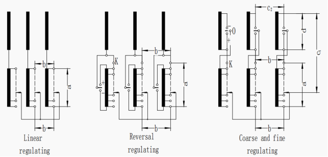
7 | Number of operating position | Linear regulation: 7、10、12、14、16、18、22、34 Reversing and coase and fine regulation: ±3~±17 | ||||||||||||||
8 | Insulation level of tap changer (kV) | Rated Voltage | 35 | 66 | 110 | 150 | 220 | |||||||||
Max.working voltage | 40.5 | 72.5 | 126 | 170 | 252 | |||||||||||
Power frequency withstand voltage(50Hz,1min) | 85 | 140 | 230 | 325 | 460 | |||||||||||
Rated lightning impulse withstand voltage(1.2/50μs) | 200 | 350 | 550 | 750 | 1050 | |||||||||||
9 | Tap selector | 4 grades of A, B, C and D according to the insulation level | ||||||||||||||
10 | Mechanical service life | Not less than 800,000 | ||||||||||||||
11 | Electrical service life | Not less than 200,000 | ||||||||||||||
12 |
Oil compartment for diverter switch | Service pressure | 3×10⁴Pa | |||||||||||||
Leakage test | No leakage under 6×10⁴Pa 24 hours | |||||||||||||||
Over pressure protection | Blasting cap blast at (4~5)×105Pa | |||||||||||||||
Protective relay | QJ4-25 oil flow speed set at 1.0m/s±10% | |||||||||||||||
13 | Oil drainage volume (L) | About 190~270 | ||||||||||||||
14 | Oil filling volume (L) | About 125~190 | ||||||||||||||
15 | Weight (kg) | About 240~350 | ||||||||||||||
16 | Motor-driven unit | MAE/MA7B | ||||||||||||||
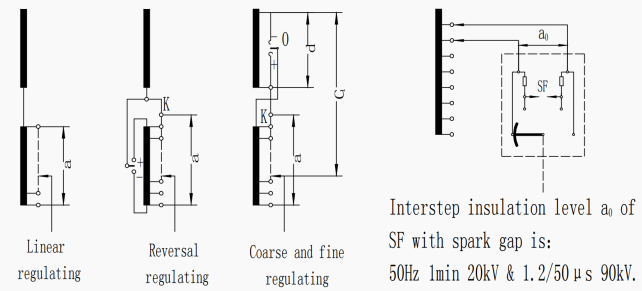
basic wiring

Voltage gradiant of every part of regulating coil
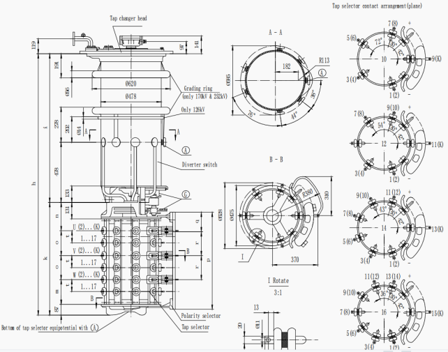
External dimension diagram of ZM
Note:
1.Step capacity = step voltage x load cuttent; Rated step capacity is the continuous permissible max.step capacity.
2.For single-phase tap changer formed by parallel of three-phase tap changer contacts; it is necaessary to take coil shounting of transformer into consideration. For ZMI800, there are two shunts. For ZMI1200 and I1500, there are three shunts.
3.The tap-changer of single phase liner regulating with 34 operating positions only have: I500A, I 800A, I1500A.
© 2026 FATO Mechanical & Electrical Co.,Ltd. All Rights Reserved. Privacy PolicyTerms of Use